Cossack Chaika: Inside Ukraine's Remarkable Sail-and-Oar Fighting Boat
A narrow wooden boat slips away from the lower Dnipro. On each side a line of oars dips into the water, a square sail waits for favourable wind, and bundles of reeds ride against the hull. Its crew can make progress under muscle power, lower its profile when necessary, and steer from either end. This is the chaika—the celebrated river-and-sea vessel associated with the Zaporozhian Cossacks of early modern Ukraine. Its importance lies not in an elaborate mechanical engine but in how ordinary materials, disciplined labour, and practical seamanship were brought together in a fast, adaptable craft.
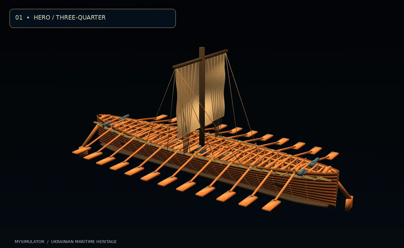
This interactive reconstruction opens that system into separately inspectable components. Visitors can reveal structural frames, isolate an oar, study the mast and lines, pull the vessel apart in an exploded view, and explore a simplified performance model. Three-dimensional details make familiar names—planking, ribs, gunwales, thwarts and steering sweeps—something that can be examined rather than merely memorised. The aim is to connect technical curiosity to the landscapes and historical circumstances in which these boats mattered.
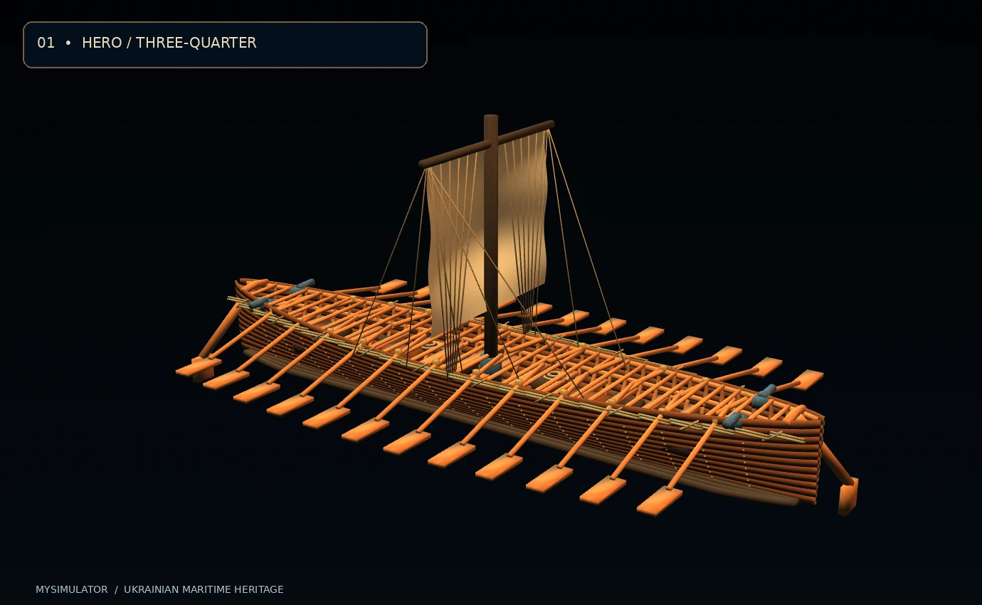
Important reconstruction notice: this exhibit represents a historically informed type, not an archaeological scan or a measured replica. Its overall length of approximately 18.4 m, illustrative beam of 3.48 m, arrangement of twelve pairs of oars and specific joinery are design choices used to explain construction. Historical sources vary, and there is no sound basis for presenting every modern CAD dimension as a known original measurement.
The lower Dnipro: a maritime frontier
The chaika belonged to a world in which the Dnipro was both a commercial route and a difficult frontier. Downriver travel from central Ukrainian towns led toward the historical rapids and the Zaporozhian settlements before opening towards the Black Sea. Small, comparatively shallow craft could exploit stretches of river, embarkations and sheltered coastal waters that presented challenges to deep-draught seagoing vessels. These geographical advantages were not a guarantee of safety: currents, rapids, weather, enemy patrols and the difficulty of replenishing supplies shaped every expedition.
The Museum of the History of Dnipro emphasises the city region's position near the historic rapids and the importance of wood transported downstream for Cossack boatbuilding. The museum also describes the Samara waterway as part of a broader network of alternative routes. These contextual details help explain why the history of the chaika cannot be separated from the geography of the lower river. A craft was more than its hull. It depended on landing points, skilled builders, forests, navigators and an organised group of people willing to row and maintain it.
The most prominent naval activity of the Zaporozhian Cossacks occurred during the late sixteenth and first half of the seventeenth centuries. Historical records associate Cossack flotillas with confrontations and raids in the wider Black Sea world, including operations against Ottoman-controlled places. The human consequences were complex: conflict, captivity, military profit, commerce and efforts to free prisoners all appear in the historiography. An educational model should describe this history rather than turn it into a simple story of effortless maritime triumph.
What the sources actually tell us
The Internet Encyclopedia of Ukraine describes a typical chaika as roughly 18–20 metres long and 3–3.5 metres wide, with a bottom hollowed from a log, raised plank sides, reed bundles attached outside, two steering devices, and a mast and sail. It also notes several small guns and a sizeable crew. Guillaume Le Vasseur de Beauplan's seventeenth-century description is an important documentary source. These facts give a strong outline but leave many details unresolved, especially if we ask for the exact position of a nail or the curvature of a particular timber.
Shipbuilding historian Viacheslav Sarychev, writing about the interactions of Balkan and Black Sea naval traditions, stresses that Cossack designs developed within a larger network of cross-cultural contact and adaptation. His discussion treats planking traditions, steering arrangements and changes in armament as part of a historical process. The vessel is therefore best understood as a class of working craft whose design could evolve, not as one immutable object built to a standard industrial blueprint.
From dugout foundation to a plank-built hull
The hull begins with the fundamental requirement of keeping water out while carrying people and stores. Historical accounts describe a dugout or hollowed-log foundation augmented by planking. Such a combination uses a solid longitudinal element for continuity while increasing capacity by adding side boards. The precise proportions of the dugout, the manner of connecting additional timbers, and the distinction between related regional boatbuilding methods are historical questions that cannot be settled by a polished digital rendering.
In this model, individual oak-coloured strakes sweep towards pointed ends. The upper parts are slightly fuller than the lower portions. This geometry creates an approximate shallow vessel in which the narrow bottom transitions to wide working gunwales. The choice to show overlapping plank edges communicates the logic of a planked hull: neighbouring boards need to work together across many metres under water pressure, bending and changes in loading. Seams have to be sealed, and timber movement must be accommodated in a craft that repeatedly becomes wet and dries.
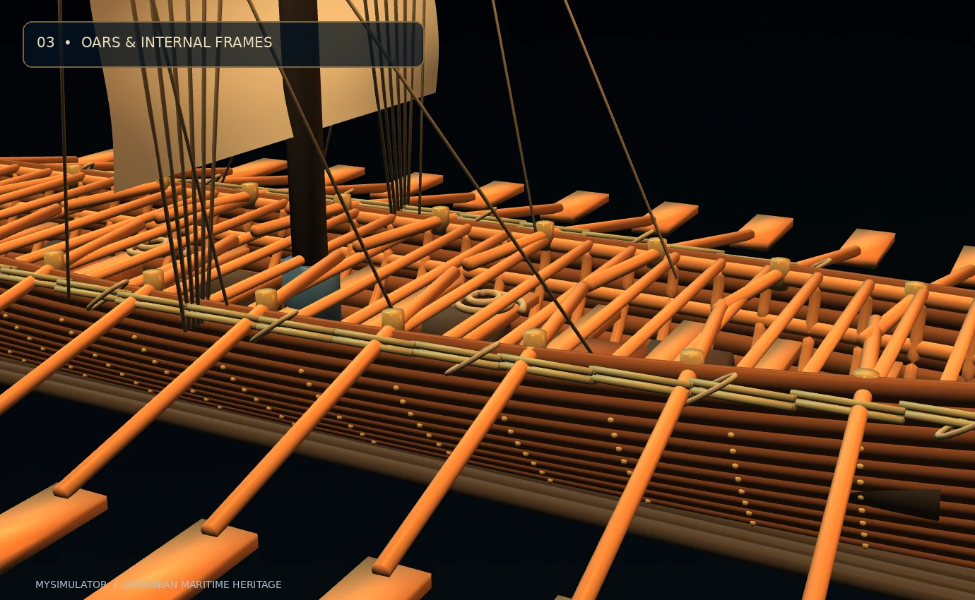
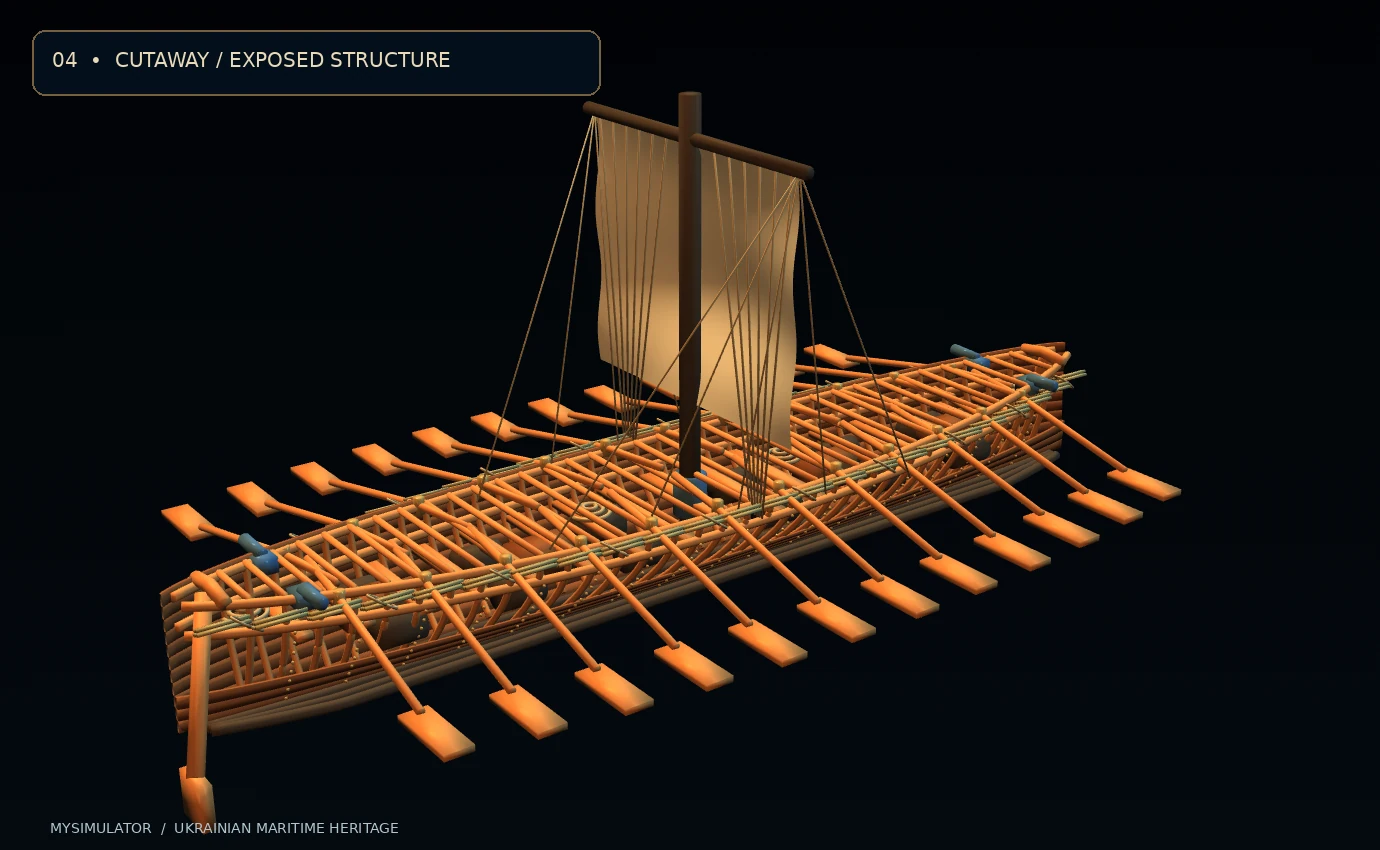
The hull is not one decorative solid. Each side is divided into selectable strakes, allowing visitors to hide the upper starboard boards. When those boards disappear, the internal form remains visible because the frames and longitudinal bottom timbers exist as separate three-dimensional members. The cutaway demonstrates the difference between an outer watertight shell and the skeleton that supports it. A curved shell is efficient partly because it distributes load across a shape rather than forcing every plank to behave like an isolated straight beam.
Frames, thwarts and internal strength
A long wooden hull experiences forces from several directions. Water pushes on the submerged shell. Rowers transmit repeated loads through the oar pivots. A mast concentrates bending and compression around its foot and supporting lines. Cargo and people load the bottom and benches. The whole vessel may hog or sag as it crosses waves. Frames and longitudinal timbers reduce the chance that these loads will distort the shell beyond its working limits.
The model contains 35 curved frames, 17 illustrative thwarts and multiple longitudinal members. They are separate components, not merely grooves painted onto an interior surface. A thwart supports a rower but also acts as a transverse tie; an inwale strengthens the internal upper edge; and the bottom members help share lengthwise loads. In the assembly experience these parts appear after the hull, so the physical logic of construction becomes clear before details of propulsion are added.
Rowing: a coordinated human propulsion system
Unlike a powered ship, a chaika depended on many people applying comparatively modest forces at the same time. Historical descriptions often place ten to fifteen pairs of oars aboard these vessels. Here twelve port and twelve starboard sweeps are modelled so that each blade, grip and shaft can be selected as one functional rowing component. An oar bears against a pivot and behaves as a lever, transferring movement from a rower's hands to the water through a much longer outboard arm.
During a working stroke the blade is immersed and moves backward relative to the boat. The water exerts a reaction force that provides forward thrust. During recovery the blade leaves the water and returns for the next stroke. In a real boat, efficiency varies with blade angle, water depth, stroke shape, body motion, crew coordination and the wake from adjacent oars. The animation uses cyclic angular movement about the individual pivot position, including a smaller vertical dipping movement, so the parts actually move around mechanically meaningful locations.
The interactive speed calculation allows the number of active oars, effective stroke force and cadence to vary. It is an openly simplified force-balance model, suitable for showing cause and effect rather than predicting a named historical voyage. The individual crews of the past cannot be assigned exact measured force outputs from written sources alone.
Two steering positions and reversing course
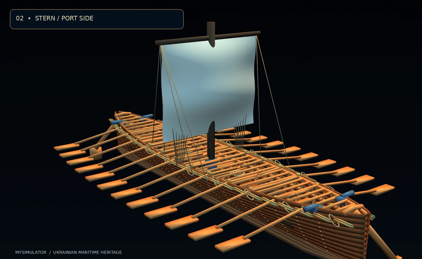
Perhaps the most memorable steering detail is the presence of devices at both ends. A double-ended working boat can avoid the time and water space needed for a conventional turn by changing the direction of propulsion and using the appropriate steering position. Historical descriptions explicitly mention a forward and an aft helm or steering oar. That feature is included as two substantial selectable components, each with an animated pivot.
Steering is not simply a matter of rotating a decorative paddle. When a steering sweep is inclined to the incoming water flow, the blade changes the local momentum of the water and experiences a transverse reaction. That lateral force creates a yawing moment around the boat's centre of mass. Its effect depends on speed, blade area, angle and how far the steering station lies from that centre. Our rudder slider changes the visible angles of the steering members, but it does not solve a complete manoeuvring dynamics model. A full turning-radius prediction would require experimental hydrodynamic coefficients and information not known for this reconstruction.
Sail, mast and rigging
Oars supply controllable propulsion, while a sail can take advantage of favourable wind without consuming the crew's energy at the same rate. The mast of a chaika could carry a sail; the museum literature and encyclopaedia identify this equipment even where they differ on specific arrangements. The exhibit uses a single square-rigged cloth suspended below a yard because this is a comprehensible historically plausible arrangement, not because one universal rig has been established for every chaika.
The sail is a real meshed surface with curved billow, while the yard, mast step, standing lines and sheets are individual meshes. The mast step restrains the lower end; stays provide support against sideways loading; lines control cloth and spar positions. The sail surface moves subtly in operation mode. Wind-driven thrust in the teaching model is intentionally conservative and assumes a useful wind direction. Close-hauled sailing, leeway, apparent-wind changes and aeroelastic cloth deformation would need a much more specialised simulation.
Reed bundles: a practical buoyancy idea
Bundles of reeds are a striking feature in descriptions of the chaika. Their importance comes from the air held between and inside plant stems. Air-filled material displaces water at low mass, providing extra reserve buoyancy if the hull becomes flooded or damaged. The bundles may also offer some protection and stand-off distance along the gunwale. That does not mean they make a boat unsinkable in every condition, nor does it establish the performance of any particular historical bundle.
The model includes separate groups of reed stalks along both sides, with individual rope lashings. These can be isolated or hidden to show how a seemingly modest element changes the overall silhouette. The material is represented by its own rough, non-metallic procedural texture. The aim is to make visitors ask an engineering question: what happens when the main watertight shell loses part of its ability to exclude water? Reserve flotation can help, but loading, stability and damage still matter.
Stores, armament and life aboard
Long journeys require food, drinking water, repair gear, ropes and space for personal equipment. Small cannon are also recorded for the type. The exhibit includes casks, supply chests, spare coils of line and four small illustrative swivel-gun assemblies. Their exact shapes, positions and quantities are a design interpretation. Such items are included to explain why internal volume and access routes are important rather than to authenticate a particular expedition.
The physics of the interactive operating model
The simulation uses a deliberately transparent equilibrium model. Let N be the number of active oars, F the illustrative effective force per oar, η the average useful-stroke factor and c the cadence in strokes per minute. A simple rowing thrust estimate is T_row = N × F × η × (c / 24), with η set to 0.52. This normalises cadence to a representative teaching reference rather than asserting that stroke power grows linearly forever. Real human performance becomes more complicated at high effort or cadence.
For a favourable wind, the sail term is T_sail = ½ ρ_air A_s C_s V_w² ε, using ρ_air = 1.225 kg/m³, illustrative sail area A_s = 22 m², C_s = 0.8 and effectiveness ε = 0.43. The model deliberately does not resolve lift and drag in all directions. Wind speed V_w is a user control in metres per second. This expression demonstrates the square-law relationship between wind speed and available aerodynamic force under fixed assumed coefficients.
The water resistance is D = ½ ρ_water C_D A_w v². In this equation water density is 1,000 kg/m³, effective resistance coefficient C_D = 1, illustrative reference area A_w = 1.72 m², and v is speed through water in metres per second. Setting T_row + T_sail = D gives v = √[2(T_row + T_sail)/(ρ_water C_D A_w)]. The model then converts metres per second into knots with 1 knot = 0.514444 m/s. Because C_D and A_w are simplified effective terms, these numbers are examples for discussion, not calibrated predictions of a chaika's sea speed.
The five live readings report speed in metres per second, speed in knots, total thrust, estimated resistance and an independent force-balance residual. The verification substitutes the computed speed back into the resistance equation and compares that value with the sum of the two thrust terms. It will read PASS when the numerical residual is negligible. This checks arithmetic consistency; it does not establish that the chosen empirical coefficients are historically correct.
Five ways to investigate the digital artefact
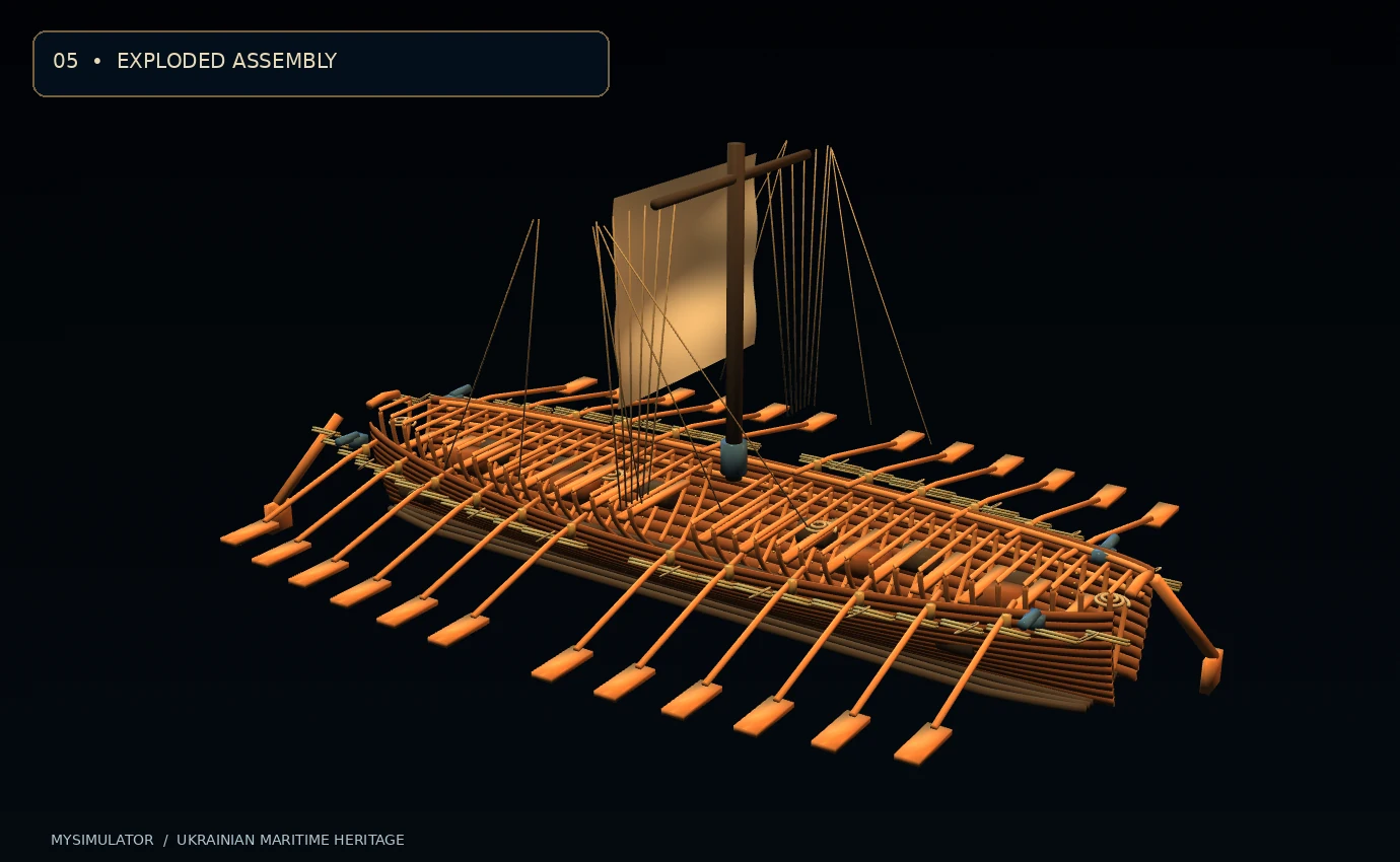
In Complete mode, orbit around the entire craft and select a named part to discover its function, material, subsystem and historical caveat. Cutaway selectively removes the higher starboard planks to reveal frames and cargo locations. Exploded applies adjustable separation to genuine meshes while preserving their original arrangement for restoration. Operation animates individual rowing sweeps and steering controls, alongside the live teaching physics. Assembly introduces ten functional subsystems in sequence, from the outer shell through the final fittings.
Every named component can be hidden or isolated, and the camera can focus on a selected item. Three GLB levels of detail help balance viewing quality and device limitations. The controls support a mouse or touch screen; desktop users may scroll to zoom, while mobile visitors can pinch and drag. A static-image fallback retains the written explanations and controls on devices without WebGL2. All bundled model, image and script paths are relative for conventional static hosting.
Looking at a reconstruction responsibly
A responsible digital heritage exhibit distinguishes three things: what documents say, what comparisons suggest and what the model builder supplied for illustration. Historical evidence supports the broad character of the Cossack chaika—its sail-and-oar propulsion, twin steering arrangements, planking and reed flotation. It does not establish our exact individual fasteners, every plank's cross-section or a laboratory-verified resistance coefficient. Presenting these uncertainties clearly makes the experience more educational, not less vivid.
The chaika deserves attention precisely because its design connected Ukrainian river geography with regional maritime expertise. It was neither a modern motorboat nor an abstract national symbol detached from labour and materials. It was a human-operated technological solution, built in a contested landscape and capable of demanding journeys. Seeing its mechanisms separately is a way to appreciate the combined achievement of builders, rowers, navigators and communities that supported them.
Frequently Asked Questions
1. What was a Cossack chaika?
A chaika was a traditional river-and-sea boat associated with the Zaporozhian Cossacks. Historical accounts describe a long wooden hull, multiple pairs of oars, a mast and sail, and steering at both ends. It was used in the wider Dnipro and Black Sea region during the early modern period.
2. How large was the vessel?
The Internet Encyclopedia of Ukraine gives representative dimensions of around 18–20 metres in length and 3–3.5 metres in width. Sources vary, so those numbers should not be treated as measurements from one authenticated surviving hull. This model adopts illustrative dimensions of 18.4 by 3.48 metres.
3. Why did it have so many oars?
Oars provided propulsion when the wind was unfavourable, permitted relatively precise manoeuvres and distributed labour among the crew. Historical descriptions commonly mention ten to fifteen pairs. The museum reconstruction represents twelve pairs and lets visitors examine each sweep separately.
4. Why were there steering devices at both ends?
Forward and aft steering could support changes of travel direction without the same turning manoeuvre required by a conventional single-ended craft. Their real behaviour depended on water flow, steering forces and rowing coordination. The two illustrated steering sweeps are functional animated parts.
5. What were the reed bundles for?
Reeds retain air and can contribute reserve buoyancy when bound into bundles. Historical accounts also associate them with protection along the sides. They were not magic flotation devices: damage, loading and stability would still govern the outcome of an accident.
6. Was the chaika a sailing boat or a rowing boat?
It combined both modes of propulsion. Oars offered dependable control, while a sail could exploit suitable winds. The relative contribution of each would vary by weather, crew effort and voyage conditions. The interactive exhibit lets the two illustrative thrust contributions change independently.
7. Is the 3D model an exact archaeological replica?
No. It is an original teaching reconstruction based on documentary descriptions and general wooden-boat engineering. The exact shape of fittings, fastener layout, casks and sails should not be mistaken for excavated or individually authenticated elements.
8. Can the simulated speed be used as a historical fact?
No. The speed comes from a transparent simplified thrust-versus-drag calculation, with assumed force and resistance coefficients. It demonstrates trends and checks its own arithmetic, but cannot substitute for controlled trials with an accurately reproduced vessel.
9. What do the five viewer modes show?
Complete mode displays the whole boat, Cutaway exposes the internal structure, Exploded separates real meshes, Operation animates moving functional parts, and Assembly steps through the ten construction subsystems. Selecting a component reveals its purpose and historical interpretation.
10. Where can I verify the history of the chaika?
Begin with the Internet Encyclopedia of Ukraine's entry on the chaika, the Museum of the History of Dnipro's exhibition text on the Cossack fleet, and Viacheslav Sarychev's research on Black Sea shipbuilding traditions. Compare the claims, note differences of date and vessel type, and distinguish documentary evidence from modern reconstructions.
Research and references
- Internet Encyclopedia of Ukraine — Chaika, Canadian Institute of Ukrainian Studies, first published in Encyclopedia of Ukraine, volume 1, 1984.
- Museum of the History of Dnipro — Cossack Fleet, exhibition material concerning Dnipro routes, Cossack expeditions and the regional context of chaika construction.
- Viacheslav Sarychev, “Frontier on the Water: Conflict and Interaction of Balkan-Black Sea Shipbuilding Traditions of the 16th and 18th Centuries,” Güneydoğu Avrupa Araştırmaları Dergisi, 35 (2020), pp. 35–42.
Illustrative 3D educational reconstruction by MySimulator.uk. This installation is not a surveyed historic vessel and is not a navigation or naval-engineering reference.