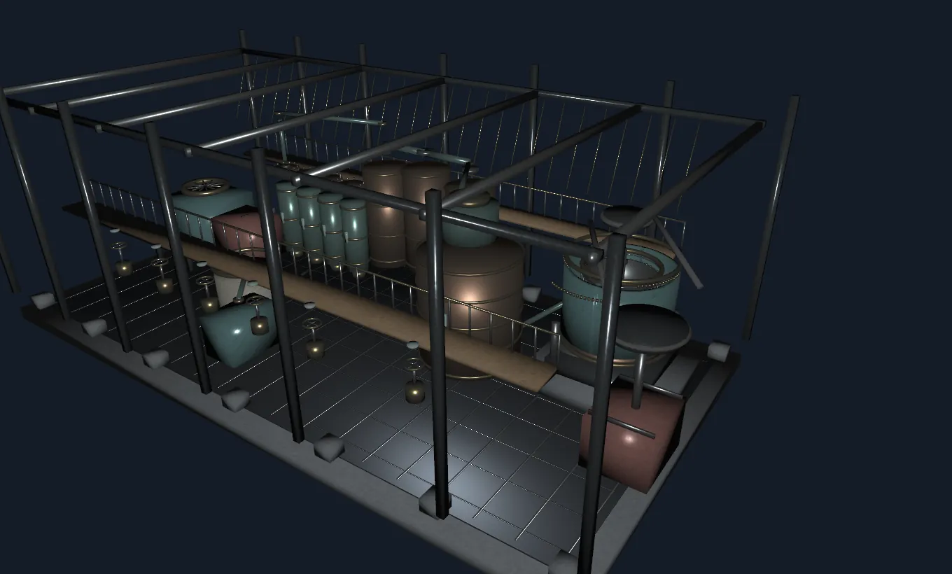
Ukraine's Sugar-Beet Factory: An Interactive Journey Through Industrial Machinery
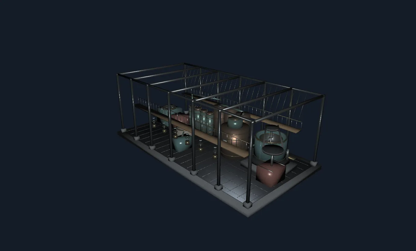
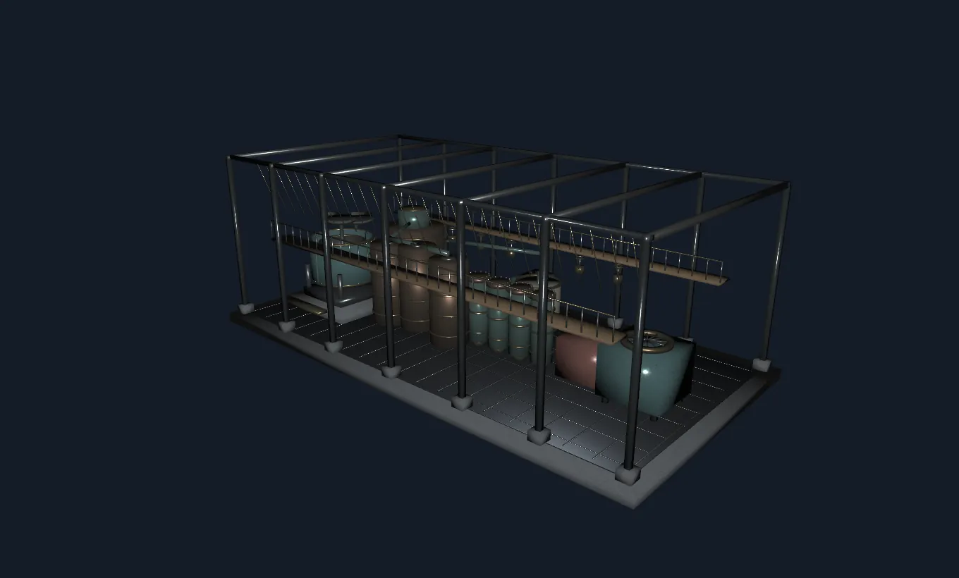
Region: Kyiv and Cherkasy, Right-Bank Ukraine. Period represented: broadly the late nineteenth and early twentieth centuries. This 3D installation is an illustrative educational reconstruction, not a survey of any identified surviving factory. Machinery spacing, vessel dimensions, colours and decorative details are illustrative.
When Ukrainian beet fields met industrial engineering
A sugar factory is an unexpected place to discover the history of precision engineering. In the nineteenth century, a sweet crop grown in Ukrainian fields supported a sophisticated network of growers, merchants, chemists, boiler operators and machine builders. Converting a muddy root into dry, sparkling crystals required a chain of apparatus with radically different jobs. Beet slices needed gentle extraction. Raw juice needed purification. Heat had to remove much of the water without destroying the valuable dissolved sucrose. Finally, microscopic crystals had to grow and be separated from sticky liquid. The machines in this exhibit explain how those jobs fit together.
Ukraine's sugar industry became particularly important in its central and Right-Bank regions, where farmland, agricultural expertise, commercial investment and expanding transport networks intersected. The Ukrainian National Academy of Sciences describes the Yakhnenko–Symyrenko, Tereshchenko and other industrial families as important participants in the industry's nineteenth-century development. Their enterprises linked manufacturing technology with finance, trade and, in many cases, philanthropic institutions. This reconstruction is a composite teaching model rather than a portrayal of any one family's works.
The geography of a sugar-producing landscape
The exhibit is associated with Kyiv and Cherkasy in Right-Bank Ukraine. These are geographic anchors for the story, not a claim that the exact arrangement depicted stood in either city. Industrial sugar beet processing also developed across other Ukrainian regions. Factory locations reflected the agricultural need to bring bulky, perishable beet roots rapidly from nearby fields. Before modern road freight, harvesting, cart transport, rail connections and fuel supplies shaped where a plant could operate economically. Factories were consequently attached to wider networks of farms, workshops, settlements and seasonal labour.
The industrial history cannot be separated from its social context. A mechanised building represented technical progress but also demanding, sometimes dangerous work. Steam, moving belts, hot liquids and rotating drums required care and maintenance. Industrial heritage therefore includes workers' knowledge as much as visible machines. The model deliberately leaves the structural frame open, making that normally hidden working environment easier to examine. It does not imply that real operating factories were roofless or that visitors could safely stand beside their machinery.
How to explore the 3D hall
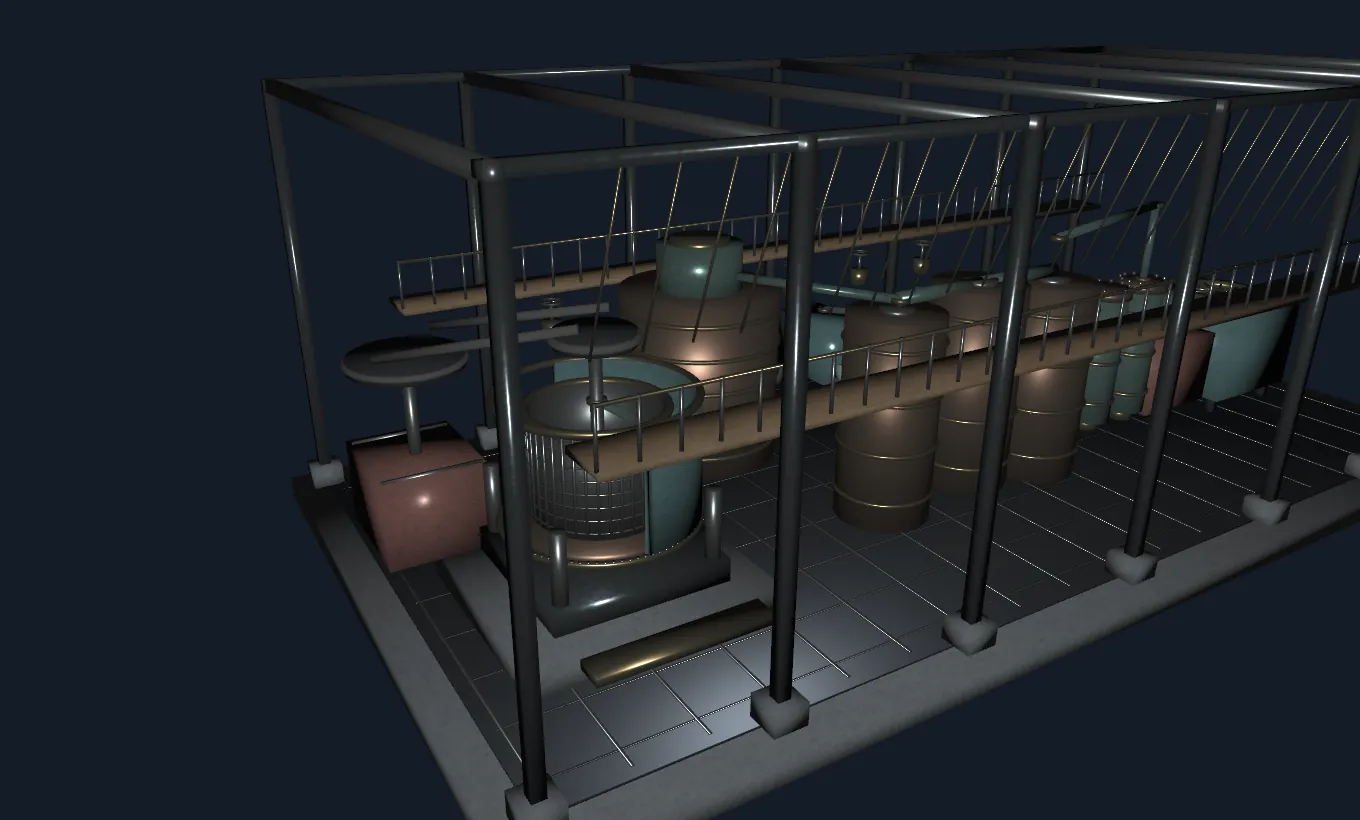
Start in Complete mode, where you can rotate the model with a mouse or finger, zoom and select individual components. The floor slab supports receiving machinery at one side, a sequence of extraction and concentration vessels through the centre, and the centrifuge near the other end. Click a shaft, screen, fitting, beam or valve to open its component card. The card identifies a material, subsystem and mechanical purpose; names are educational rather than copied from a historic factory inventory.
Use Cutaway to remove the centrifuge's front casing and inspect its real mesh-screen basket. Exploded separates built components geometrically so that relationships become clearer. Operation turns the moving basket, spindle, output pulley, blade wheel and mixer; decorative framing remains stationary. Assembly rebuilds the factory by subsystem, starting with its foundation and ending with instrumentation. These are interactive interpretations of a single model, not photographs of five unrelated objects.
Stage one: receiving, cleaning and slicing beet
Beet arrives with soil and plant residues. Industrial processes therefore begin with receiving, washing and sorting before the crop becomes a uniform feedstock. Our small hopper marks this transfer point; its grill and frame are educational details. Once the crop is cleaned, sharp rotating knives cut it into long, thin pieces commonly called cossettes. Their shape matters: increasing exposed surface area helps soluble sugar diffuse into water while an excessively fine mash would be difficult to handle and separate.
The slicer in the reconstruction has a rotating disc, an enclosing housing, a set of individually modelled blades and an inlet throat. The exact knife geometry is stylised. In Operation mode, the blade disc rotates in proportion to the centrifuge's demonstration drive setting, but this coupling is a teaching simplification and not a claim that a historic production line used that exact transmission. Real factories coordinated several separate drive systems at different rates. The conceptual lesson is the same: uniform cutting is a preparation step, not the sugar-separation step itself.
Stage two: extraction by diffusion
The cut beet contains dissolved sucrose inside plant tissue. Diffusion uses heated water to extract that soluble material. Under the simplest explanation, molecules move from zones of higher concentration toward zones of lower concentration. Factory equipment goes further by moving the sliced beet and extraction water in a carefully arranged flow, often counter-current, to recover sugar efficiently while limiting wasted water. Residence time, temperature, sanitation and equipment geometry all matter; high temperature is not a substitute for good process control.
The four capped vertical vessels on the model represent a historical-style extraction battery. Bridges link their upper fittings, and their lower drains show where liquid might leave a chamber. This layout is illustrative rather than an exact engineering drawing of a named installation. Later industrial systems commonly used very different continuous diffuser layouts. The viewer emphasises the idea of multiple stages, close connections and accessible maintenance fittings. A slice of beet does not magically become a sugar crystal here: the initial liquid still carries many dissolved and suspended non-sugar substances.
Stage three: clarification and filtration
Raw extraction juice is not clear, purified sucrose. It carries colour, minerals, organic compounds and small solids. Sugar factories use chemical clarification and filtration to remove impurities before concentrating the valuable liquid. In a common beet-sugar treatment sequence, milk of lime is mixed into the juice and carbon dioxide is introduced. Calcium carbonate precipitates and helps capture or carry certain unwanted substances. Filtration then removes the precipitate and associated impurities. The chemistry must be carefully controlled to avoid unnecessary losses and processing problems.
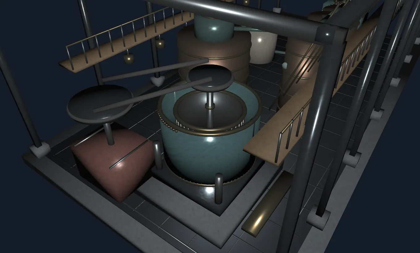
Look for the broad mixing vessel, central stirrer shaft, radial vanes, filter press and removable plates in the 3D hall. The mixer rotates as a low-speed demonstrator in operation mode. The filter plates are separate selectable meshes, even though the simplified vessel omits much internal plumbing. A real industrial clarifier would include additional valves, transfer pumps, measuring instruments and settling or filtration facilities. Here, the objective is to distinguish three functions: mechanical mixing, chemical treatment and physical removal of the resulting solids.
Stage four: multi-effect evaporation
After clarification, the juice still contains a great deal of water. Evaporation concentrates it until sugar production becomes practical. Boiling water consumes significant energy, so factory engineers developed arrangements that reuse heat. In multi-effect evaporation, vapour created in one vessel can help heat another vessel operated at a lower pressure. The descending pressure allows the later stage to boil at a lower temperature. This energy cascade reduces the fresh steam requirement compared with independent single-effect boiling vessels.
Three large cylindrical drums represent this heat-saving principle. Copper-coloured surfaces, internal tubes, bolted bands, instrument faces and a shared upper connection help visitors read the equipment as a connected process. The relationships between pressure, saturation temperature and heat transfer are physically grounded. Individual vessel sizes and heating surface areas are not measured representations of a specific Ukrainian plant. Actual historical factories evolved over time, so this model intentionally compresses technology from a broad period into one comprehensible arrangement. It is better treated as an industrial engineering lesson than as a dated factory blueprint.
Stage five: crystallisation inside a vacuum pan
Concentrated syrup has still not turned into dry sugar. To produce solid sucrose, the liquid is brought toward supersaturation, a state in which more sucrose is present than can remain dissolved under the prevailing conditions. Properly controlled crystal formation allows sucrose to leave the liquid phase and grow into larger, recoverable particles. Uncontrolled nucleation can produce troublesome small crystals, so industrial operators manage temperature, pressure, syrup concentration and sometimes seed crystals with considerable care.
The broad central vacuum pan illustrates this stage. Its rounded vessel, neck, access cover and inspection glazing are drawn at an accessible scale, while internal heating coils provide an explanation of where energy enters. In an actual vacuum system, pressure is deliberately reduced to control boiling behaviour. The term vacuum does not mean complete absence of gas or magical cooling; it describes pressure lower than the surrounding atmosphere. As crystals form, the resulting mixture of solid sugar and remaining mother liquor is commonly known as massecuite, which is ready for mechanical separation.
Stage six: the centrifuge and its hidden basket
The centrifuge is the main mechanical exhibit. A stationary outer housing surrounds a perforated basket driven by a vertical spindle. The massecuite enters the rotating basket. As rotational speed rises, the contained mixture must undergo an inward centripetal acceleration to remain on a circular path. Under the resulting pressure distribution and relative motion, liquid is driven through the basket's perforations while the larger sugar crystals are retained. The liquid drains to a collection pan, while the crystals remain available for further washing or drying.
In Cutaway mode, the outer front wall disappears and reveals the genuine mesh-surrounded basket, axial spindle, retaining rings, structural spokes and lower collection pan. Mesh elements are not a painted image: they are separate 3D geometry. The basket, shaft and upper pulley rotate together when the machine operates. The outer casing and concrete plinth remain fixed, as they should. Our basket construction is simplified: it does not model fluid film dynamics, every screen opening or the detailed fatigue analysis needed for a production centrifuge.
What rotational speed actually changes
A point moving at angular speed omega and radius r requires inward radial acceleration a = omega²r. Angular speed in radians per second is omega = 2πN/60, where N is revolutions per minute. The corresponding acceleration relative to normal gravity is RCF = omega²r/g, with g = 9.80665 m/s² in this simulation. The tangential speed is v = omega r. These are textbook equations, and they are implemented directly by the sliders. Increasing the radius at fixed rpm raises both tangential speed and radial acceleration; doubling rpm at fixed radius produces four times the radial acceleration.
The controls also approximate radial force as F = m omega²r and rotational kinetic energy as E = (1/2) m r² omega². The energy formula assumes the selected mass is concentrated in a thin ring at the chosen radius. Real baskets have a complicated mass distribution and may contain an uneven charge, so neither expression is a design recommendation. The on-screen verification independently calculates the RCF using v²/(rg). If the two algebraically equivalent approaches agree within floating-point tolerance, the internal demonstration check passes. It does not certify industrial safety.
Understanding the transmission system
Machinery does not rotate itself. The educational drive assembly includes an enclosing machine case, a vertical output shaft, a large pulley, a smaller driven pulley, two visible belt runs and a set of spindle bearing features. The imagined driver represents the general idea of an industrial prime mover; the model does not identify an authentic steam engine, electric motor or drive system at a documented works. A rotating belt transmits tangential force through contact and friction, which in turn creates torque at the driven shaft.
For an ideal no-slip belt drive, tangential belt speed at each pulley rim is equal, giving N1D1 = N2D2 for rotational rates N and pulley diameters D. The model assigns a fixed illustrative ratio for visible animation and holds the belt centreline geometrically static. This conveys linked movement but is not a physically solved flexible-belt simulation. It is important to separate a correct kinematic principle from an artistic mechanical approximation. Bearings, guards, alignment and safe clearances would all be central to a real machine's operation and would need detailed engineering certification.
People, enterprise and Ukrainian technical education
The growth of sugar processing shaped more than farms and factories. It supported machinery purchases, financial institutions, agricultural experimentation, railway-related commerce and educational philanthropy. Kyiv Polytechnic Institute's historical material records the involvement of figures from the sugar business among supporters of higher technical education in Kyiv at the end of the nineteenth century. The National Academy of Sciences also discusses the industry's role in enterprise development and broader social investment. These accounts explain why a piece of industrial equipment belongs in an exhibition about Ukrainian history.
Historical narratives need care, however. Entrepreneurship, investment and technical innovation existed alongside uneven working conditions and profound social change. A virtual machine cannot adequately represent every worker, season or community. Nor should a generic reconstruction be attributed to an exact owner merely because that owner is historically prominent. This installation therefore uses regional context and documents its illustrative nature while placing mechanical principles in the foreground. The history is real; the room arrangement is interpretive.
Reading the reconstruction responsibly
This is a designed exhibit made in 2026 for educational exploration. It is not a scanned artefact, original nineteenth-century factory plan, reconstruction licensed by a museum, or historically authenticated collection of machine measurements. Some units and proportions were chosen for visual clarity, and the demonstration drive aggregates stages that in reality would operate under independent control. Important modern safety equipment, foundations and fluid systems are not modelled to production engineering standards. It would be unsafe to construct a machine using these visuals alone.
The distinction between a historical fact, a well-established physical law and an illustrative reconstruction is a productive part of learning. Historical research can tell us where sugar factories mattered and how their business networks developed. Industrial references explain why diffusion, evaporators, vacuum pans and centrifuges appear in the process. Mechanics shows how a rotor's speed and radius determine acceleration. The visible details then give those concepts a memorable spatial form. Explore the model, change parameters, try the independent calculation check and use the quiz to test what each stage accomplishes.
Frequently asked questions
1. Why did sugar beet become important to Ukraine's industrial history?
Sugar beet could be grown in productive agricultural regions, then processed into a valuable, transportable product. During the nineteenth century, processing businesses expanded around farms, industrial equipment, financing and commercial networks. Entrepreneurs in the Kyiv and Cherkasy area participated in those developments. The subject therefore joins agriculture, chemistry, industrial mechanics and Ukrainian economic history. No single region or family can represent the entire history of the industry.
2. Is this an exact reconstruction of a Ukrainian factory?
No. It is a clearly labelled educational composite inspired by industrial machinery and Ukrainian sugar-making history. The proportions, position of vessels, structural members, drive case and individual bolts are illustrations rather than digitised measurements from a named factory. Documented process stages and mathematical relationships are distinguished from invented visual geometry. The aim is to teach the system's operation without misrepresenting its provenance.
3. What is a beet cossette?
A cossette is a relatively thin piece of sliced sugar beet prepared for extraction. Slicing increases the accessible surface area through which dissolved sucrose can move into process water. Factories aim for a shape that encourages extraction without producing an unmanageable pulp. The model displays a drum-like cutter and several separate blades so visitors can identify why cutting belongs before diffusion.
4. What is diffusion doing inside the extraction vessels?
Diffusion transfers soluble sucrose from beet tissue into heated water. In industrial practice the extraction process is arranged to achieve good sugar recovery without using an excessive volume of water. Flow arrangement, temperature, residence time, hygiene and beet preparation all matter. The model's four-vessel battery shows connected equipment, but it is not a scale design of any particular diffuser.
5. Why are lime and carbon dioxide involved in clarification?
In a standard sugar beet purification process, milk of lime and carbon dioxide help create precipitated calcium carbonate and remove or capture impurities in the liquid. Filters separate the solid material from the juice. This chemistry improves the quality of the syrup entering the evaporators. The exhibit's mixing shaft and filter plates visualise the mechanical steps; they cannot demonstrate every chemical reaction directly.
6. Why are there multiple evaporators instead of one enormous boiler?
Evaporation is energy-intensive. By operating at successively lower pressures, multi-effect equipment can use vapour from one stage to heat another. That reduces the need for fresh steam and can improve energy efficiency. The linked copper-toned vessels model this principle rather than one dated factory layout. Visitors should think of them as a flow network with deliberate temperature and pressure differences.
7. What does a vacuum pan do in sugar production?
A vacuum pan concentrates syrup and manages the conditions under which sugar crystals grow. Lower-than-atmospheric pressure makes it possible to boil at controlled temperatures, while concentration and seeding influence crystallisation. The product is a mixture of crystals and mother liquor, not instant dry granulated sugar. A separate centrifuge is therefore still needed to remove much of the syrup from the crystals.
8. Why does centrifugal acceleration increase so quickly with speed?
Radial acceleration is a = omega²r. The squared angular-speed term means that doubling the rpm at fixed radius quadruples the radial acceleration. A larger radius also increases radial acceleration when rpm remains constant. In the exhibit, you can move the rpm slider and see the result directly in multiples of Earth's standard gravitational acceleration, called RCF or g-force.
9. Is the force readout safe for designing a real centrifuge?
No. The readout applies ideal textbook formulas to an illustrative mass and radius. A real rotating basket requires verified materials, balancing, load distribution, guard design, fatigue analysis, shaft and bearing calculations, overspeed protection and compliance with relevant machinery standards. The independent RCF check only demonstrates agreement between two equivalent formulas; it is not a mechanical safety validation or a performance guarantee.
10. Does the 3D exhibit work on phones and without WebGL?
On a capable device, the responsive WebGL2 viewer supports orbiting, zooming, selection, operation and the other exhibit modes. Mobile devices start with a reduced-detail GLB by default. The educational sliders, explanatory content and quiz also remain accessible if the graphics context is unavailable. In that case the fallback is a schematic rather than full interactive 3D; some controls that require selecting geometry cannot provide the same experience.
Research and provenance
- National Academy of Sciences of Ukraine — The European Spirit of Ukrainian Capitalism: Sugar Kings (2024)
- Igor Sikorsky Kyiv Polytechnic Institute — Pages from the institution's history
- Ukrainian National Scientific Agricultural Library — Right-Bank Ukraine food-industry research (2023)
- FAO / EBRD Agribusiness Handbooks, volume 4, Sugar Beets / White Sugar (1999), pp. 35–44
- World Bank — Sugar manufacturing and its production stages
Source scope: the historical references establish industrial context, and the engineering references establish the generic beet-sugar processing stages. No source is presented as evidence that the exact depicted reconstruction once existed.